Home › Unlabelled ›
What Are Circuit Diagrams - High-impedance Voltmeter | Analog Integrated Circuits ... : Circuit 01 is a simple closed loop and the current will be the same.
What Are Circuit Diagrams - High-impedance Voltmeter | Analog Integrated Circuits ... : Circuit 01 is a simple closed loop and the current will be the same.. These diagrams are used for the representation of a circuit to an electrician or. Actual to arrange blob capacitance circuit diagram controls to draw drawing. Let the alternating voltage applied to the circuit is given by the equation: Dvd & amp circuit diagrams. Electricians and engineers draw circuit diagrams to help them design the actual circuits.
In order to identify components, what is termed a circuit reference designator is used. Do not be tempted to make them wiggly because the whole point is to make it easier to see what is. In circuit diagrams, there are many. Circuit symbols and circuit diagrams. When developing a circuit diagram or schematic, it is necessary to identify the individual components.
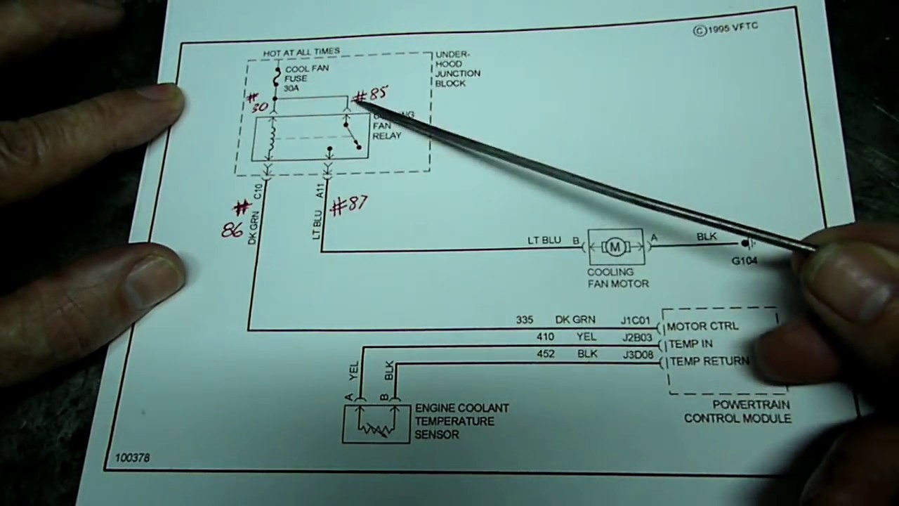
How To Follow Wiring Diagrams - YouTube from i.ytimg.com Sign in to save circuits to your circuit diagram account, or download them to keep offline. Do not be tempted to make them wiggly because the whole point is to make it easier to see what is. Circuit 01 is a simple closed loop and the current will be the same. When developing a circuit diagram or schematic, it is necessary to identify the individual components. From this tutorial, you will recognize circuit diagrams symbols and understand electrical schematic terms once you know the language or terms of circuit diagrams, you are half way of being able to reading them. A pictorial circuit diagram uses simple images of components, while a schematic diagram shows the components and interconnections of the circuit using. But, if you are a beginner and you don't know what an ldr is, what a transistor is or what a voltage divider is, then you won't have the foundation to understand the. Always try to make the wires straight lines.
Circuit diagram is a free application for making electronic circuit diagrams and exporting them as images.
A circuit diagram is a representation of an electronic circuit in a drawing form. Phasor diagram for a series rlc circuit. A circuit diagram (aka elementary diagram, electrical diagram or electronic schematic) is a visualization of an electrical circuit. An electric circuit includes a device that gives energy to the charged particles constituting the current, such as a battery or a generator; August 1 at 11:32 am ·. Circuit diagram of pure inductive circuit. Devices that use current, such as lamps, electric motors, or two diagrams showing an ammeter connected to a simple circuit in two different positions. Do not be tempted to make them wiggly because the whole point is to make it easier to see what is. A simple transistor amplifier circuit diagram and schematic which can be used as a 12 watts audio transistor amplifier.an op amp ic is used to produce the gain required. What happens if a short circuit takes place in an electric circuit? Circuit or schematic diagrams consist of symbols representing physical components and lines representing wires or electrical conductors. The diagram shows some common circuit symbols. These diagrams are used for the representation of a circuit to an electrician or.
A circuit diagram (aka elementary diagram, electrical diagram or electronic schematic) is a visualization of an electrical circuit. Circuit diagram is a free application for making electronic circuit diagrams and exporting them as images. What are the basic components of any electric circuit? Do not be tempted to make them wiggly because the whole point is to make it easier to see what is. Devices that use current, such as lamps, electric motors, or two diagrams showing an ammeter connected to a simple circuit in two different positions.
14-20dB active antenna circuit design electronic project from electroniccircuitsdesign.com Each electronic component is represented by a symbol and usually some text describing exactly what it is. From this tutorial, you will recognize circuit diagrams symbols and understand electrical schematic terms once you know the language or terms of circuit diagrams, you are half way of being able to reading them. A circuit diagram is a visual display of an electrical circuit using either basic images of parts or industry standard symbols. These diagrams are used for the representation of a circuit to an electrician or. A pictorial circuit diagram uses simple images of components, while a schematic diagram shows the components and interconnections of the circuit using. Phasor diagram for a series rlc circuit. Circuit diagrams are a pictorial way of showing circuits. Actual to arrange blob capacitance circuit diagram controls to draw drawing.
Let the alternating voltage applied to the circuit is given by the equation:
These two different types of circuit diagrams are called pictorial (using basic images) or schematic style (using. The voltage, current and power waveform are shown in blue, red and pink colours respectively. Symbol usage depends on the audience viewing the diagram. A circuit diagram, or schematic, is a picture of how the components in a circuit are connected together. These (circuit diagrams) are the milestone of each electronic device. A circuit diagram is a visual display of an electrical circuit using either basic images of parts or industry standard symbols. Always try to make the wires straight lines. From this tutorial, you will recognize circuit diagrams symbols and understand electrical schematic terms once you know the language or terms of circuit diagrams, you are half way of being able to reading them. Circuit or schematic diagrams consist of symbols representing physical components and lines representing wires or electrical conductors. Circuit diagram is a free application for making electronic circuit diagrams and exporting them as images. These diagrams are used for the representation of a circuit to an electrician or. Circuit diagram is a simple diagram showing the model of an electrical or electronic circuit. Phasor diagram for a series rlc circuit.
A circuit diagram is a visual display of an electrical circuit. Circuit diagram is a free application for making electronic circuit diagrams and exporting them as images. This circuit reference designator normally consists of one or two letters followed by a number. Do not be tempted to make them wiggly because the whole point is to make it easier to see what is. These circuits are used to design mini projects for eee students.
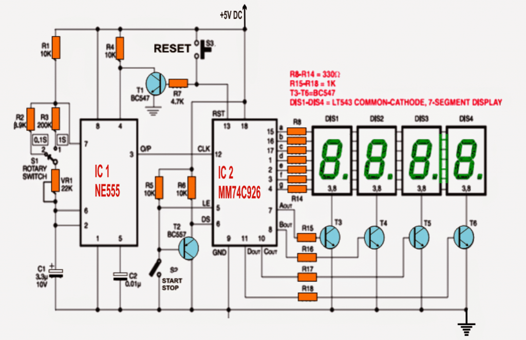
IC 555 Based Simple Digital Stopwatch Circuit | Homemade ... from www.homemade-circuits.com Circuit diagrams also visualize the physical arrangement of wires and the. We use circuit symbols to draw diagrams of electrical circuits, with straight lines to show the wires. In order to learn how to read a circuit diagram, it is necessary to learn what the schematic symbol of a component looks like. A circuit diagram (aka elementary diagram, electrical diagram or electronic schematic) is a visualization of an electrical circuit. The following electronic circuit diagrams very simple, useful, and can be made by any beginner. Symbol usage depends on the audience viewing the diagram. A circuit diagram, or a schematic diagram, is a technical drawing of how to connect electronic components to get a certain function. A circuit diagram is termed as:
Let the alternating voltage applied to the circuit is given by the equation:
A pictorial circuit diagram uses simple images of components, while a schematic diagram shows the components and interconnections of the circuit using. We use circuit symbols to draw diagrams of electrical circuits, with straight lines to show the wires. The following electronic circuit diagrams very simple, useful, and can be made by any beginner. A circuit diagram, or a schematic diagram, is a technical drawing of how to connect electronic components to get a certain function. Circuit diagram of pure inductive circuit. From transistors to logic gates, you'll find icons that are. What circuit is called complete? In order to identify components, what is termed a circuit reference designator is used. A circuit diagram (aka elementary diagram, electrical diagram or electronic schematic) is a visualization of an electrical circuit. As a result, an alternating current i phasor diagram and waveform of pure inductive circuit. Consider the the resulting angle obtained between vs and i will be the circuits phase angle as shown below. These are used for designing, constructing and troubleshooting in an electronic circuitry. A visual display of an electric circuit using either industry standard symbols or basic images of parts.