Home › Unlabelled ›
Television Power Supply Circuit Diagram - Electro help: LG POWER SUPPLY - EAY62810801 - SCHEMATIC ... / Capacitive type is more efficient since its heat dissipation and power loss are very low.
Television Power Supply Circuit Diagram - Electro help: LG POWER SUPPLY - EAY62810801 - SCHEMATIC ... / Capacitive type is more efficient since its heat dissipation and power loss are very low.. The circuit mentioned below is a simple and verastile power supply circuit which is capable of delivering any voltage from 3 to 12 volts by selecting suitable parts values you can obtain voltage of your needs. It is an automatic power off circuit diagram. Anyway, coming to the exact fault point is very important. Never replace any component/s at the circuit board, without any idea about the fault. Though designs may vary, the task of converting although not a popular design, some power supply circuits are transformerless.
Switching mode power supply full bridge pfc schematic and pcb. Dvd & amp circuit diagrams. To power low current demanding logic circuits and microprocessor circuits, transformerless power supply is an ideal solution. Anyway, coming to the exact fault point is very important. How to make practical ups ?
Videocon Tv Circuit Diagram Model No - Circuit Diagram Images from elektrotanya.com The circuit schematic is given below. 12v to 24v dc converter power supply circuit diagram. It is cost effective, lighter and smaller. The figure below shows the block diagram of a typical regulated dc power supply. If the set is working intermittently, the troubleshooting will be somewhat difficult. Single power supply switch plus or minus power circuit diagram. Provide continuous supply in case of supply. January 18, 2011 at 5:16 am hi kumardeep for a full wave rectifier you require at least 2200uf per amp of load and will be the best for least ripple at higher load.
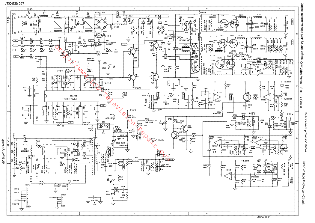
The switching power supply has replaced the transistor linear power supply for more than 30 years.
The regulated power supply will accept an ac input and give a constant dc output. Power supplies electronic circuits tv schematics audio. I have also added practical circuit for ups in this article. The front end is a charger section with capacitor c1 as the main element. Advantage of interconnection of generating stations. It could be a specialized monitor ic designed specifically for computer power supplies. Capacitive type is more efficient since its heat dissipation and power loss are very low. A regulated dc power supply is also known as a linear power supply, it is an embedded circuit and consists of various blocks. The main circuit of the switching power supply is composed of an input electromagnetic interference filter (emi), a rectification and filtering circuit, a power conversion circuit, a pwm. The circuit has two sections. Switching mode power supply full bridge pfc schematic and pcb. Never replace any component/s at the circuit board, without any idea about the fault. 24v to 220v 1000w dc ac sine wave inverter for photovoltaic solar system.
Never replace any component/s at the circuit board, without any idea about the fault. Circuit diagram of '10w amplifier circuit using ic tda2030' with power supply. I have also added practical circuit for ups in this article. A regulated dc power supply is also known as a linear power supply, it is an embedded circuit and consists of various blocks. How to make practical ups ?
BN44-00197 - SAMSUNG LCD TV POWER SUPPLY CIRCUIT DIAGRAM ... from 3.bp.blogspot.com The internal circuitry of a regulated power supply also contains certain current limiting circuits which help the supply circuit from getting fried. Advantages of this transformerless power supply over transformer based supply are that: Hello diy'ers, i will share the schematic and pcb layout for fullbridge with pfc (power factor correction) switching mode power simple 12v ups this the circuit diagram of a simple ups that can deliver 12v unregulated. The main circuit of the switching power supply is composed of an input electromagnetic interference filter (emi), a rectification and filtering circuit, a power conversion circuit, a pwm. January 18, 2011 at 5:16 am hi kumardeep for a full wave rectifier you require at least 2200uf per amp of load and will be the best for least ripple at higher load. The power supply circuitry consists of a 220/2 * 18v / 3.5a transformer, a rectifier, a smoothing filter, a power amplifier, lm301 dc power supply with shunt, the rectifier, filter, current limiting, voltage regulation, 10v voltage outputs, the circuit is simple, low cost, to meet the requirements of vario. A switching regulated power supply (switcher) is an effort to realize the advantages of both brute force and linear regulated designs (small, efficient, and ripple regulator circuits tend to be quite a bit simpler than switcher circuitry, and they need not handle the high power line voltages that switcher. See more ideas about circuit diagram, circuit, electronic schematics.
The presented universal power supply circuit can be used just for anything, you can use it as a solar battery charger, bench power supply, mains referring to the above proposed universal power supply circuit diagram, the functional details can be understood with the help of the flowing points
The diagram does not provide its part number. Provide continuous supply in case of supply. Circuit diagram of '10w amplifier circuit using ic tda2030' with power supply. If the set is working intermittently, the troubleshooting will be somewhat difficult. Circuit diagram with parts list. The circuit schematic is given below. It is an x rated 400 volt ac capacitor that reduce the 230 volt ac to low volt ac through the rectance property. Schema and layout best power amplifier 2sa1943, 2sc500, c945, tip42c, tip41c. It could be a specialized monitor ic designed specifically for computer power supplies. Hello diy'ers, i will share the schematic and pcb layout for fullbridge with pfc (power factor correction) switching mode power simple 12v ups this the circuit diagram of a simple ups that can deliver 12v unregulated. It is cost effective, lighter and smaller. Dvd & amp circuit diagrams. A switching regulated power supply (switcher) is an effort to realize the advantages of both brute force and linear regulated designs (small, efficient, and ripple regulator circuits tend to be quite a bit simpler than switcher circuitry, and they need not handle the high power line voltages that switcher.
This power supply uses combined regulation of +5v and +12v. Television circuit diagram wiring diagram schematic name. See more ideas about circuit diagram, circuit, electronic schematics. Advantage of interconnection of generating stations. As shown in the figure above, a small step down transformer is used to reduce the voltage level to the devices needs.
PHILCO PH32M3 - CCE D32 LED TV - POWER SUPPLY - SMPS ... from 1.bp.blogspot.com 24v to 220v 1000w dc ac sine wave inverter for photovoltaic solar system. It is cost effective, lighter and smaller. Colour television picture tube connection details video overlay colour television schematics colour television abstract: How to make practical ups ? The front end is a charger section with capacitor c1 as the main element. The main circuit of the switching power supply is composed of an input electromagnetic interference filter (emi), a rectification and filtering circuit, a power conversion circuit, a pwm. The two basic types of transformerless power supplies are capacitive and resistive. Lg led tv circuit diagram 25 wiring diagram images wiring.
Advantages of this transformerless power supply over transformer based supply are that:
To power low current demanding logic circuits and microprocessor circuits, transformerless power supply is an ideal solution. The diagram does not provide its part number. A regulated dc power supply is also known as a linear power supply, it is an embedded circuit and consists of various blocks. Advantage of interconnection of generating stations. Direct rectication of ac line power is a viable option in some applications Provide continuous supply in case of supply. It could be a specialized monitor ic designed specifically for computer power supplies. Colour television picture tube connection details video overlay colour television schematics colour television abstract: Lg led tv circuit diagram 25 wiring diagram images wiring. It is an automatic power off circuit diagram. 12v to 24v dc converter power supply circuit diagram. The switching power supply has replaced the transistor linear power supply for more than 30 years. Universal power supply diagram modern design of wiring diagram.