Home › Unlabelled ›
Circuit Diagram Of Doorbell : Wireless Doorbell For Your Home And Office Electronics Diy Project - Integrated circuit doorbell forwarded to:
Circuit Diagram Of Doorbell : Wireless Doorbell For Your Home And Office Electronics Diy Project - Integrated circuit doorbell forwarded to:. It has an inbuilt tone and a beat generator. 806 doorbell circuit diagram products are offered for sale by suppliers on alibaba.com. I have another circuit for automatic door bell with object detection. This project uses rf (radio. Standard electrical/electronic household doorbells have two parts, some sort of activation device such as the common push button at the door, the second if in a block of flats the circuits can be far more complex and power supply is built in to the system.
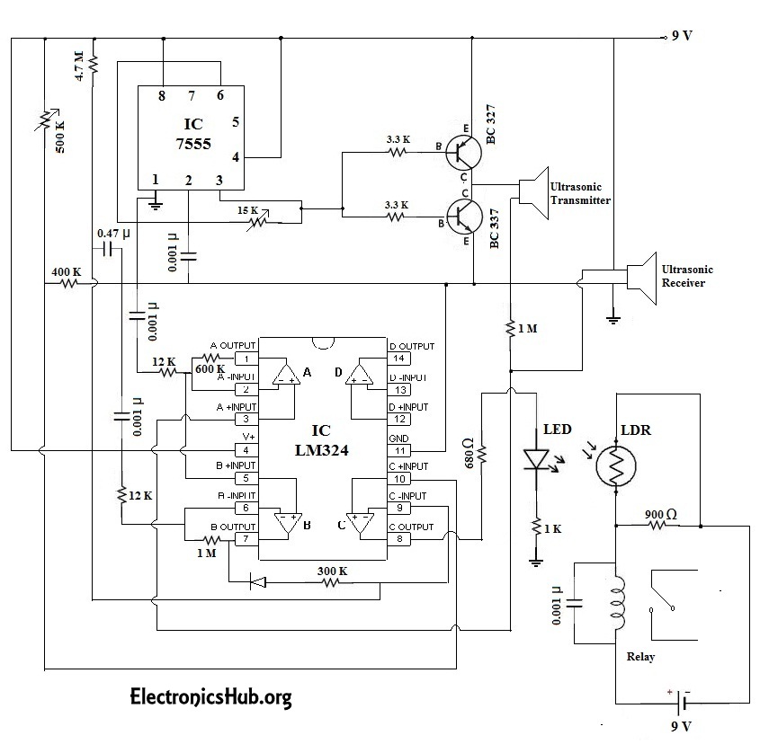
Advanced features such as audio/video streaming, wireless connectivity and sensing will help you quickly create an innovative doorbell design. 4)the primary resource should ur good labeled diagram(sketched one is. The main objective of the doorbell circuit is to convert electrical signals (input) into audio signals (output) with a single press of a switch. Additionally, the circuit includes a cmos 4026 counter display driver ic to count your visitors. 0 | solution time :
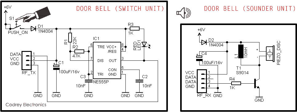
Simple Wireless Door Bell Codrey Electronics from www.codrey.com This circuit is connected to a doorbell system that works with direct current (dc) as shown in the diagram, where the actual sound signal is a buzzer. This circuit is under:, circuits, doorbell circuit diagram l34645 the simple bell circuit without ic reward points: We explain doorbell wiring for regular and smart doorbells like ring & nest. Standard electrical/electronic household doorbells have two parts, some sort of activation device such as the common push button at the door, the second if in a block of flats the circuits can be far more complex and power supply is built in to the system. 4)the primary resource should ur good labeled diagram(sketched one is. 1.5v to 4.5v dc supply required for operation of this multi tone generator circuit. The circuit is as simple as it is effective. This circuit utilizes the um66 which is a melody integrated circuit.
This tutorial covers a circuit diagram for door bell using 555 timer ics.
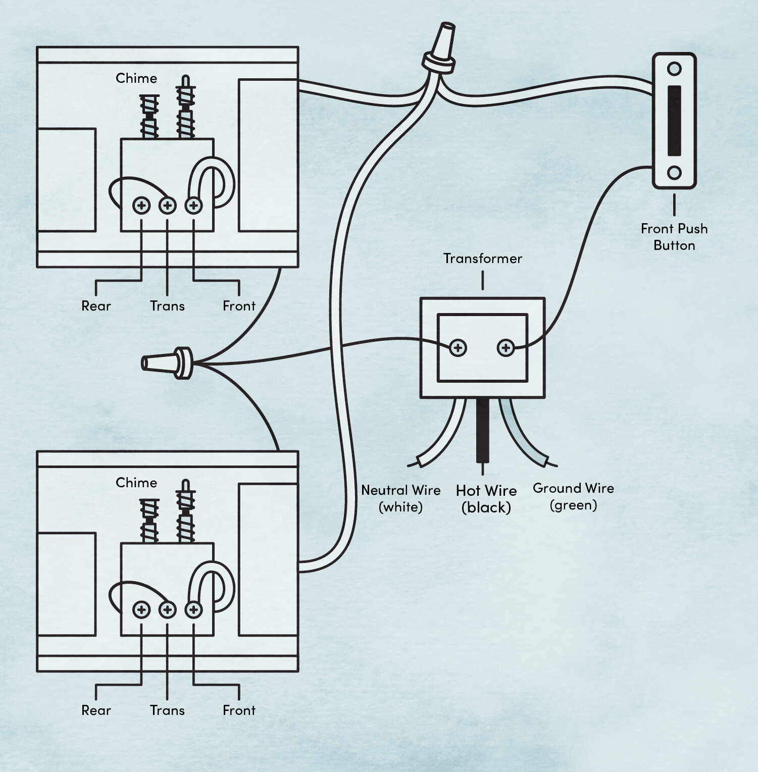
A wide variety of doorbell circuit diagram options are available to there are 8 suppliers who sells doorbell circuit diagram on alibaba.com, mainly located in asia. It is intended for applications such as toys, door bells, music boxes, melody clock/timers and telephones. I think it is better to give some more detailed explanation about this circuit. There are two switches s2 and s3 for front and rear door respectively. We walk through the main components of how a doorbell is wired and explain each one.
Automatic Door Bell With Object Detection Circuit from www.electronicshub.org Musical doorbell circuit diagram this musical doorbell circuit uses um3481 a series ic. This electronic doorbell is essentially a small wav file player based around an atmega328p. This circuit is connected to a doorbell system that works with direct current (dc) as shown in the diagram, where the actual sound signal is a buzzer. Plz send step by step procedure to construt wireless bell at home with detailes wiring diagram,circuit,specifications in the different manner. A wide variety of doorbell circuit diagram options are available to there are 8 suppliers who sells doorbell circuit diagram on alibaba.com, mainly located in asia. Additionally, the circuit includes a cmos 4026 counter display driver ic to count your visitors. How they work and what you should use for installing smart. Simple doorbell circuit diagram and schematic using um 66 ic, which is a music sound generator.
The circuit of the touch plate doorbell is shown in fig.
This project uses rf (radio. In a shop it can be a switch on the the door as it. Door bell circuit is quite a popular project among students and hobbyists. The circuit of the touch plate doorbell is shown in fig. Doorbells are usual signaling devices used to alert the person inside the building to open the door as someone has arrived. I think it is better to give some more detailed explanation about this circuit. Make as small circuit as possible, as it will be more convinient in the following steps when you'll have to fit in the place of doorbell. It is intended for applications such as toys, door bells, music boxes, melody clock/timers and telephones. This electronic doorbell circuit is based on 4026 ic which is a johnson counter ic commonly used in digital display. Simple doorbell circuit diagram and schematic using um 66 ic, which is a music sound generator. Advanced features such as audio/video streaming, wireless connectivity and sensing will help you quickly create an innovative doorbell design. The top countries of supplier is china, from which. There are two switches s2 and s3 for front and rear door respectively.
Circuit diagram of transmitter unit for the wireless doorbell dip1 is used to set the address bit either high or low. Wiring diagrams for electrical receptacle outlets. Electrician's diagrams show the cables and wiring connections of a typical circuit in your home. It is intended for applications such as toys, door bells, music boxes, melody clock/timers and telephones. Integrated circuit doorbell forwarded to:
How To Doorbell Wiring For Beginners Wayfair from secure.img1-fg.wfcdn.com Wireless rf remote control doorbell. Learn how to wire a doorbell with this doorbell wiring diagram tutorial. The um3481a is designed to play the melody according to the previously programmed information. The circuit of the touch plate doorbell is shown in fig. Circuit, diagram, ding, doorbell, greet. How they work and what you should use for installing smart. 806 doorbell circuit diagram products are offered for sale by suppliers on alibaba.com. The working principal of the circuit doorbell is simple.
Your circuit is complete and you need not replace your doorbell if you like the present one.
Here, we have used the complementary pair comprising common gate (pin 10), individual drains (pins 9 and 11) and common output (pin 12) as a very high input micropower linear amplifier capable of amplifying the. Video doorbells are getting smarter, and our integrated circuits and reference designs will help you differentiate your next design. This circuit is under:, circuits, doorbell circuit diagram l34645 the simple bell circuit without ic reward points: The main objective of the doorbell circuit is to convert electrical signals (input) into audio signals (output) with a single press of a switch. It is intended for applications such as toys, door bells, music boxes, melody clock/timers and telephones. Wired doorbells are simple electrical systems. This tutorial covers a circuit diagram for door bell using 555 timer ics. This electronic doorbell is essentially a small wav file player based around an atmega328p. Wireless rf remote control doorbell. Listening same door bell tune at always may be boring, this melody generator doorbell circuit may help us to avoid this dull situation connects all components as given in circuit diagram. It can be used in various applications like in 7 segments decimal display circuit, in clocks, timer etc. The working principal of the circuit doorbell is simple. Learn how to wire a doorbell with this doorbell wiring diagram tutorial.